Installation Guide:
GS3 Connected Machine Retrofit Kit
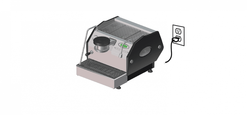
Step one: Turn machine off and unplug for safety
Step two: Remove electronic board box.
First, remove the screws on the rear of the GS3, then remove the rear panel as well as the left and right panels.

Step three: Open the Board Box
Remove the screws to open the board box. Remove the white/red and white/blue wires from the main power switch.

Step four: Remove connectors and board from the box
Disconnect all the connectors from the board, labelling them prior. Including how the SSR’s are wired. Then remove the 4 x screws holding the board in place, then remove the board. Remove all the connections from the SSR’s and capacitor in order to free up the board box.

Step five: Installing the Gateway
Place the gateway as shown on the picture.
Use the 4 holes of the gateway in order to mark the position of the holes that we need to drill on the board box. Use a 2,5mm drill to make the holes that will support the gateway.
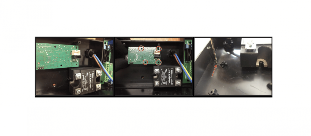
Step six: Installing the Gateway
Insert the screws through the bottom of the board box and hand tight the 4 supports with the round section at the top. Install the gateway, then install the provided screws (x4) to mount it to the supports.

Step seven: Installing the new board
Install the new board using the screws previously removed. Then, reconnect all the connections in the same locations as the old board.
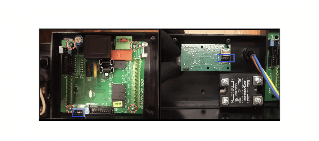
Step eight: Installing the new board
Connect the flat ribbon cable from the new board to the gateway. Reconnect all the connections to the SSR’s and capacitor

Step nine: Connecting the new capacitor
The capacitor has the terminals labelled on the base of it. Using the included wire tree, connect the corresponding connectors to the relevant terminals. Install the capacitor on the right frame with a cable tie.

Step ten: Connecting the new capacitor
Connect the black and white cable from the capacitor to the open terminals on the switch. Plug the male connectors from the capacitor into the two connectors that were previously on the switch, as shown.

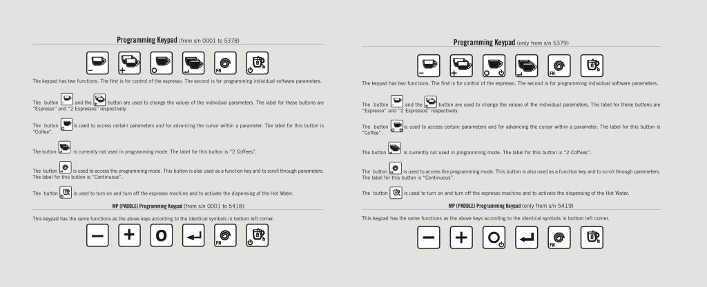
PLEASE NOTE
GS3AV machines prior to SN5379 and GS3MP machines prior to SN5419 will have button arrangements different than the current button locations, and will need either a new display/button pad assembly or button decals depending upon the state of the current assembly. This can be determined by the technician performing the upgrade. Please be aware that older machines may have other issues that will need to be addressed during the install and that a consultation with a technician is highly recommended before attempting the install. Please contact [email protected] for more info and a referral to a competent technician.